Miniature circuit breakers perform the dual functions of a switch and a fuse. They can open a circuit for safety or maintenance reasons simply by switching their toggle levers to the OFF position. As substitutes for fuses, they provide automatic circuit protection and need not be replaced after a dangerous overcurrent has passed or a short circuit has been corrected
The ampere rating defines the maximum current the circuit breaker can carry without tripping. For typical miniature circuit breakers this rating is 15 to 125 A. In residential applications, single-pole breakers protect 20-V branch circuits, and two-pole breakers protect 240-V branch circuits.
The voltage rating of a circuit breaker can be higher than the circuit voltage, but never lower. The fault current interruption rating (or short-circuit interrupting rating) is the maximum available fault current that could be expected from the overhead or padmounted distribution transformer outside a residence. If the transformer can produce 10,000 A of current, each breaker in the loadcenter should be rated for at least 10,000 A. While residential breakers have ratings of 10,000, 22,000, 42,000, and 65,000 A, the available fault current for most single-family homes rarely exceeds 10,000 A.
Each miniature or branch circuit breaker, as shown in the cutaway view below Figure includes a bimetal strip or element. When this strip is heated to its threshold temperature, it bends enough to unlatch a mechanism and open the breaker’s electrical contacts.When the contacts open, the toggle on the circuit breaker automatically switches to the OFF position. This, in turn, opens the branch circuit.

These small circuit breakers can be reset manually after they have tripped. As with fuses, the ampere rating of the breaker must match the ampacity of the circuit it protects. These circuit breakers are also called plug-in breakers, because they are connected to the loadcenter by plugging them into the bus-bar tabs or stabs.
A high-quality thermal circuit breaker will open a 10,000-A fault at 240 V AC in 40 to 50 ms. Under simple overload conditions, the deflection of a bimetal thermal sensing element within the circuit breaker causes the circuit to open when a preset temperature threshold is reached. Rising temperature in a bimetal element is caused principally by load current (I2R) heating. The thermal element also factors in the heating or cooling effects caused by nearby heating or cooling sources (furnaces or air conditioners), as well as changes in the ambient temperature.
The size of the bimetal thermal element and its configuration, shape, and electrical resistivity determine the current capacity of a circuit breaker. The most common element is a “sandwich” of two or three different metals. The low-expansion side, for example, might be Invar, the center might be copper or nickel, and there is a wide choice of metals for the high-expansion side.
Some thermal circuit breakers rated for 5 A or lower contain heater coils adjacent to or in series with the bimetal element. These heater coils compensate for the lower anticipated heating action of a fault in a low-current circuit. They augment element self-heating to maintain the temperature of the thermal element closer to the preset threshold temperature, to speed up the trip response in the presence of overcurrent.
Some miniature thermal circuit breakers also contain a magnetic element to accelerate tripping in the presence of an exceptionally fast rising overload. That condition increases current flow fast enough to create a magnetic field in a small electromagnet or solenoid that pulls in a mechanical linkage to unlatch the contacts and trip the breaker before the bimetal element can respond and deflect. The basic elements of a thermal-magnetic circuit breaker are shown in the simplified diagram below Figure.
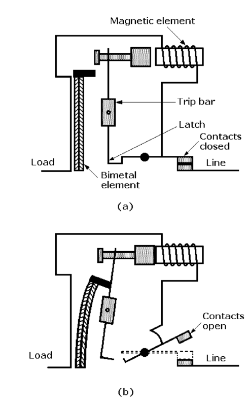
The normal condition of the Miniature circuit breakers are illustrated in above Figure (a) .The bimetal element in these breakers responds the same way to overcurrent as the element in a simple thermal breaker. As shown in above Figure (b) , the bimetal element deflects in proportion to the heating effect of the current passing through the wire in close proximity to it. As in thermal breakers, the bimetal element will open a 10,000-A fault at 240 V AC in 40 to 50 ms. The bending element unlatches the contact mechanism, opening the contacts.
By contrast, the small solenoid magnetic element has a few turns of low-resistance wire in series with the wire adjacent to the thermal element, which has little effect on the impedance of the breaker. In the presence of rapidly rising current, a magnetic field forms around the solenoid, causing it to pull in the trip bar, which unlatches the contacts and opens them. This element responds 4 times faster than the bimetal element, or in about 10 ms.
Molded-case and miniature circuit breakers are designed to operate in elevated temperature environments such as those encountered inside a breaker panel carrying load. If the panel door is left open for a long period of time or is removed, the interior of the panel will cool to a lower temperature. This additional cooling will allow the breaker’s thermal element to exceed its rated continuous current. This could mean that the load it is protecting could overheat.
Circuit breaker manufacturers have different methods for attaching their breakers to the “hot” bus bars. Most breakers have some form of notch on one end of their lower surfaces and conductive clips on the other ends. Typical loadcenter “hot” bus bars have projections alternating from the inner sides of the bars. As stated earlier, the ends of these projections are bent outward at right angles to form stabs. The breakers are installed by hooking the notch at one end under a rail and pressing the conductive clips down over the stabs to make low-resistance contacts with the “hot” bus bars.
Single- and double-pole breakers are most widely used in loadcenters. Single-pole units, rated for 120/240 V AC, are designed to be plugged onto a single bus stab to obtain 120 V between one of the “hot” bus legs and the neutral bus, These breakers are available in ratings from 15 to 70 A, but ratings of 15 and 20 A are most commonly used in homes. They are available in 1-in.-wide full-size, dual 1-in. widths, and half-size 1/2-in. widths.
Some single-pole units are UL listed as HACR type, for air-conditioning, heating, and refrigeration equipment service, as well as being UL listed for SWD (switching duty) for switching 120-V AC fluorescent lighting loads.
Two-pole breakers are rated 120/240 or 240 V AC. Standard sizes are plugged onto two adjacent stabs to obtain 240 V between both parallel “hot” bus bars. They are available with 10- to 125-V ratings. These breakers have a single common trip, and many are HACR type. Some circuit breaker applications by current rating are
- 15 and 20 A: Protection of baseboard heaters and pumps
- 30 A: Protection of water heaters, dryers, and air-conditioning equipment
- 40 to 50 A: Protection of ranges and stoves
- 50 A or more: Protection of electric heaters
Three-pole breakers rated for 240 V require three spaces for contact with three stabs, and they also have common toggle trips. They are typically listed as HACR type for use with air-conditioning, heating, and refrigeration equipment.
The number of single-pole circuit breakers that can be installed in a loadcenter is limited by the number of stabs on the bus bars. For example, a loadcenter with six stabs can accommodate 12 full-size, single-pole branch circuit breakers that are each 1 in. wide.
If the stab is notched, half-size branch circuit breakers can be used. Half-size circuit breakers allow two single-pole circuit breakers to be installed in the space originally intended for a 1-in.-wide full-size breaker. Each half-size unit is only 1/2 in. wide. Where they are allowed by the local electrical code, these breakers function as well as full-size breakers and offer the added convenience of a more compact installation.
Some local inspectors do not allow half-size circuit breakers because it is possible that they could overload the loadcenter or unbalance the system. To balance the loads, circuit breakers must be evenly allocated by current rating to each side of the stab. It is important that the maximum continuous amperes and available fault current be known when specifying loadcenters and overcurrent protection devices. There are two ways to meet this requirement: full-rating or series-rating method
- Full-rating method:Circuit protection devices are specified with ratings equal to or greater than the available fault current. For example, if a building has 22,000 A of fault current available at the service entrance, every circuit protection device must be rated at 22,000A.
- Series-rated method:The main upstream circuit protection device must have an interrupting rating equal to or greater than the available fault current of the system. Downstream devices connected in series can be rated at lower values. For example, a building with 20,000 A of available fault current might have the breaker at the service entrance rated for 20,00 A and additional downstream breakers rated at 10,000 A.